F. Wagner February 2009
StateWORKS: Break States in the VFSM Executor
Introduction
We sometimes encounter the necessity for an explicit break of the VFSM Executor when specifying a state machine to be realized by a StateWORKS run-time system. To discuss the problem let's have a look at the flow chart in Figure 1 showing the VFSM execution model.
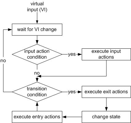
Figure 1: VFSM execution model
This basic assumption of the VFSM state machine model is to work in the execution loop using a copy of the initial virtual input (VI) as it is when entering the loop. The flowchart shows also that the VFSM executor performs all the valid state transitions it finds while entering the consecutive states, in one sequence. The Executor stays in the loop: transition condition – execute exit actions – change state – execute entry actions until there are no more transitions due, i.e. all transition conditions become false. Thus, several transitions might be performed in a state machine, almost instantaneously. This can, in some cases, cause an indefinite loop between a state which issues a command and the state which acknowledges it, as discussed in the next section by means of a simple example. The VFSM Executor is guarded against this failure by breaking the loop after certain number (default: 10) of passes in the loop.
Whenever we encounter such a problem we can always find some workaround that bypasses the difficulty, usually by adding extra states. StateWORKS now offers an elegant solution in a form of a Break property assignable to any state, and for brevity we shall refer to these as "Break states".
Break state
The use of the Break state can be illustrated with a simple example which repeats an action, each time it is stimulated by a command. The command, which we call CmdRepeat, should change the state from Init to Repeat. In the state Repeat something is done and the system should then return to the state Init. That action can be repeated many times.
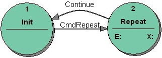
Figure 2: Repeat: the bad state transition diagram
A bad solution is shown in Figure 2. On receiving the CmdRepeat the state machine goes to the state Repeat (see the state transition table in Figure 3) where it does something and returns immediately to the state Init. In spite of clearing the command the state machine stays in the loop as it still uses the original virtual input with the CmdRepeat. The VFSM Executor terminates the loop supervising the number of transitions. Note that the DoSomething output will be performed only once as the output value does not change. Thus, in effect the required behavior has been achieved but in a very inelegant way.
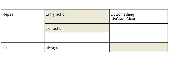
Figure 3: Repeat: the bad state transition table of the state Repeat
An alternative solution is to define a state as a Break state. Executing the Break state the VFSM Executor does not follow the execution path shown in Figure 1 but it breaks it after the first state transition, returning to the wait for VI change point. A state is marked as a Break one by a prefix _B_ which is reserved for that purpose.
Figure 4 Shows the previous state machine using the Break state. In that case the state _B_Repeat has the Break feature. On entering the state _B_Repeat the DoSomething action is carried out and the command is cleared. Although the state machine leaves the execution path after this state transition it enters the execution path again, being triggered by the event Cmd0 (command cleared). It returns then to the state Init where it waits for another CmdRepeat.
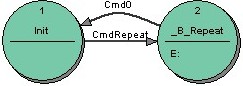
Figure 4: Repeat: The correct state transition diagram using a Break state _B_Repeat
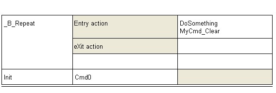
Figure 5: Repeat: the state transition table of the state _B_Repeat
Pulse generator example
We show another example of a state machine which requires the Break functionality. It is a pulse generator that is to oscillate continuously between two states with a frequency determined by a Timer timeout. Figure 6 shows the first possible but bad concept.
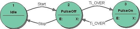
Figure 6: Pulse generator: the bad state transition diagram
The generation begins with the command Start and is terminated by the command Stop. The state machine should oscillate between states PulseOff and PulseOn: setting a digital output to High in the state PulseOn and to Low in the states PulseOff will realize the pulse generator.
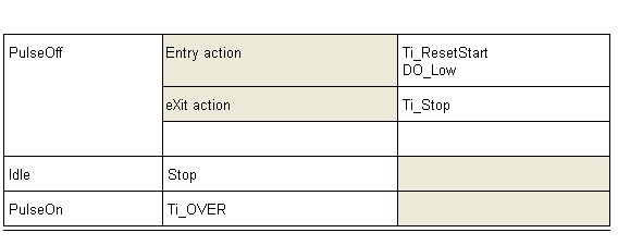
Figure 7: PulseGenerator - the bad state transition table of the state PulseOff
According to the state transition table in Figure 7 on entering the state PulseOff a timer is started and if the timer elapses the state machine goes to the state PulseOn. If a similar state transition table is specified for the state PulseOn (see Figure 8) the state machine will oscillate a few times between these two states: not at the frequency defined by the timer but at a much higher frequency determined by the system features. Then it waits in the state PulseOff for another timeout. Thus, we get an incorrect behavior.
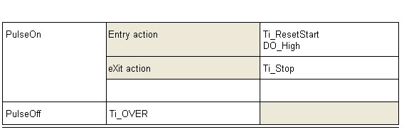
Figure 8: PulseGenerator - the bad state transition table of the state PulseOn
Using a Break state
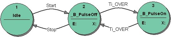
Figure 9: PulseGenerator: The correct state transition diagram using Break states
To make the system function according to our wishes, we use a Break state as shown in Figure 9. In that case both states On and Off have the Break feature. The state transition diagrams as well as the state transition tables of the “bad solution” (see Figure 6 and Figure 7) and the solution using Break states are the same. In the latter case the correct behavior is achieved by changing the execution path of the VFSM Executor, as described below.
We would like to mention in passing that the break problem does not arise if we use two timers: one in the state PulseOn and another one in the state PulseOff. This will be a possible workaround if we do not use the Break facilities offered by the StateWORKS development environment. It is fully correct but requires two timers instead of a one. This solution would be anyway required if we want to have a different cycle length for Off and On states.
Effects on the VFSM execution models
Using ready-made run-time systems like RTDB based applications we have to take into account the execution model of the system. The VFSM Execution model as shown in Figure 1 allows several state transitions to be triggered by a single event. This feature has a side effect in situations discussed in the technical note. StateWORKS Studio offers solutions: a Break state as a standard technique to be used while specifying a state machine. Figure 10 shows the revised flowchart of the VFSM Executor, capable of breaking the execution path.
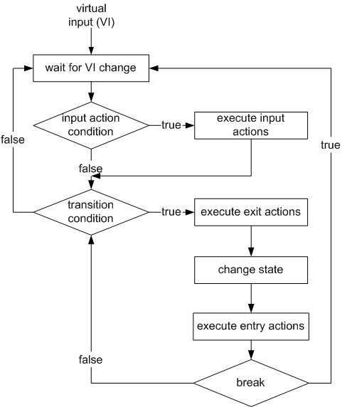
Figure 10: VFSM execution model with the Break feature
Conclusions
The solutions for (rare) cases of the breaking problem as presented in the technical note seem to be optimal. If required we may use the Break state. In order to use Break states we changed intentionally the execution logic of the VFSM Executor. The obligatory prefix to the state name signals this specific point in the specification. This selfdocumenting feature is very important and is in line with the StateWORKS specification philosophy: the specification has to show all details so as to make behavior as understandable as possible. The aspect is a "must" in any software which needs to stay maintainable.
References
[1] Wagner, F. et al., Modeling Software with Finite State Machines – A Practical Approach, Auerbach Publications, New York, 2006.
 download PDF version