
Overcoming Limitations in PLC Programming
Introduction
Section titled “Introduction”The document starts with an analysis of an example taken from the IEC document, which specifies the IEC 61131-3 standard (PLC) ↗ for programming Programmable Logic Controllers (PLC). The example uses the terms states and transitions, suggesting the use of the state machine concept in PLC design. The example is then realized as a state machine using StateWORKS, illustrating how the functionality can be completed and improved.
Comparing the StateWORKS solution with the approach presented in the IEC document we may formulate some reflections about the evolution taking place in the PLC world and suggest further changes encouraging a transition from intuitive to model based design.
GRAVEL example from IEC 61131 document – critical analysis
Section titled “GRAVEL example from IEC 61131 document – critical analysis”The description of the control problem from the IEC document begins:
A control system is to be used to measure an operator-specified amount of gravel from a silo into an intermediate bin, and to convey the gravel after measurement from the bin into a truck…
The required operations can be specified referring to Figure 1.

Figure 1: Gravel system
The description suggests the designed system uses momentary-action push buttons (like keyboard buttons, i.e. they have one stable position). The JOG button is not shown on the console panel; we assume that it is mounted somewhere close to the conveyor and used in emergency and service cases.
The requirements are: the ON button switches on the automatic control, the OFF button stops it. If the automatic control is on the FILL button starts filling of the bin. The filling terminates automatically if the required (set by a thumb wheel) amount of gravel is in the bin. When the bin is filled and the truck is on the ramp (detected by a limit switch) the LOAD button switches on the truck loading: the conveyor motor is started and after a while when it reaches the full speed the dumping of the bin contents begins. When the bin is empty (detected by a limit switch) the conveyor runs still for a while so that the entire load of gravel is loaded onto the truck. At any time the loading can be stopped and reinitialized if the truck leaves the ramp or if the automatic control is off.
The automatic control “on” and the presence of the truck on the ramp are each to be signalled by a lamp. The conveyor running and silo empty are to be signalled by a blinking lamp. In addition, a siren is to signal that the silo is empty. The siren can be acknowledged by a button for a certain time: if the silo stays empty the siren will be restarted.
The implementation does not mention explicitly the concept of state machines but uses the word “state” and “transition”. Thus, it is relatively easy to identify the main state machine in the design. The control system is realized as SFC (Structured Function Chart) using ST (Structured Text) language elements. The SFC has two representations: a text (the actual program) and a graph (a kind of flowchart with symbols of logical elements like gates and flip-flops).
The states are declared with the keyword STEP, the initial state with INITIAL_STEP and the transition with TRANSITION. Hence, the initial step looks like:
INITIAL_STEP START ; END_STEPTRANSITION FROM START TO FILL_BIN := FILL_PB & CONTROL.X ; END_TRANSITION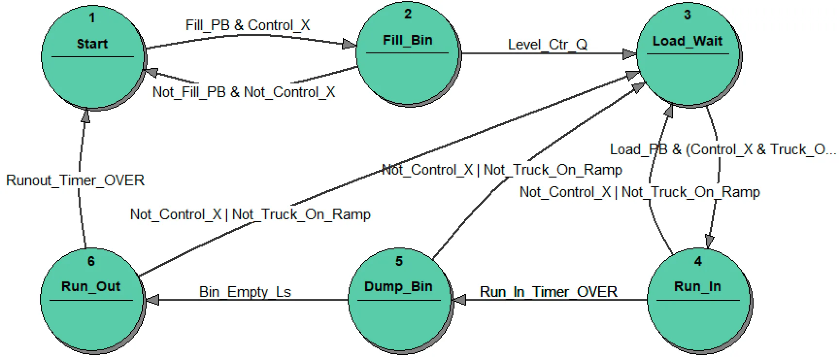
Figure 2: IEC Gravel state machine
Analyzing the SFC program, we identify 4 state machines, or we could say 3 state machines and one combinational system. The first state machine (let’s call it Gravel) is programmed under the title “Major operating states” and is shown in Figure 2. This state machine changes its state as triggered by inputs but does not control anything directly (well, the declaration:
:= TIMER.T >= RUN_TIME:starts effectively the timer and waits for the timeout to perform the transition).
To keep the correspondence between the code in the ICE document and the state transition diagram as close as possible we use the original variable names from the IEC document. The meaning of the names which might be confusing for the reader are:
Control_X→ Automatic Control isOn,Not_Control_X→ Automatic Control isOff,Fill_PB→FILLPush Button is pressed,Not_Fill_PB→FILLPush Button is not pressed,Level_Ctrl_Q→ Required level in Bin is reached.
Other names are more or less understandable.
If there is a “major system” we would expect there will be some “other systems” too. No, the second state machine (let’s call it Control) is programmed under the title “Control state sequencing” and is shown in Figure 3. This state machine remembers the lastly pushed button ON or OFF and its state is used in the combinational system as well as in the state machine Gravel in logical conditions. The Control state machine implements the conveyor motor control and switching of the blinking lamp signalling that the silo is empty. A section drawn as two delay components assures the blink timer function, and could be considered as a state machine having only two states.
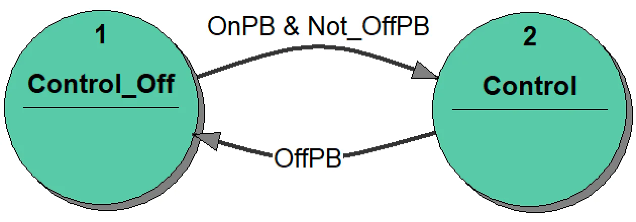
Figure 3: IEC Control state machine
The combinational system (let’s call it Action) decodes the situation using the states of the state machines plus inputs and determines outputs. The entire control system is shown in Figure 4.
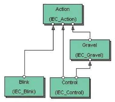
Figure 4: The Gravel control system as SFC
Some comments about the implementation:
- The use of the
FILLpush button is not clear. If it is a 1-position push button than the operator has to push the button all the time during the filling; when he removes his finger from the button filling will be interrupted and the system returns to the stateStart. The other solution would be to use a 2-position button. - The control of the silo valve is shown in SFC but missing in the program (should be opened in the state
Fill_Binand closed otherwise). - The control of the bin valve is shown in SFC but missing in the program (should be opened in the state
Dump_Binand closed otherwise). - The control of the siren signalling empty silo is shown in SFC in such a way that a hardware designer would not accept it (a flip-flop with both R and S inputs active and assuming that the input R wins). The implementation in the program is so complex we can only believe that it works.
- The test of the conveyor lamp is missing.
- The design has some weak points. For instance, when loading is started it cannot be broken, but the entire content of the bin must be loaded onto the truck. The other not nice solution is that if the run-out is interrupted and the conveyor starts again the run-out time is calculated always from the beginning.
- The problem mentioned in the previous point may be truly unpleasant in case of limit switch malfunctions. For instance, if the
BinEmptysensor does not work there is no way to reach the initialStartstate except restarting the system. - There are no precautions for detecting and reacting to the malfunctions.
- There is no way to switch of the siren if the silo is empty: the siren whine can be only interrupted for a while.
- Last comments relate to the syntax of the SFC representation. I would have never managed to understand the functioning of ST language elements:
Blink,BlankandPulsewithout the SFC diagram. And that was only understandable for me because of my hardware background that I still have not forgotten. I cannot save myself a (rhetorical) question why PLC programmer do not protest against that kind of user unfriendly syntax. In general, it makes a funny impression to keep for any price hardware diagram that should explain totally unreadable program.
Omissions discussed above are typical for sunny-day-scenarios where we implement the sequences that should happen. The unexpected situation will be later dealt with in some way: often by code.
A state machine as a replacement for markers
Section titled “A state machine as a replacement for markers”PLC programming has always used markers to store information about the past. Markers are equivalent to flags in code. The problem with markers is the same as with any flags: they are difficult to control if their number increases. The form of the control system in the example corresponds directly to the concept of markers: the steps (i.e. states) are in effect treated as a better way to organize markers. But effectively, the code defines a state machine.
A code in the IEC document is developed in the following way: we design in some way a state machine which reflects a certain “sequence”. Then we build a combinational circuit which is built using the state of the state machine and inputs. The problem lies in the understanding and design of the “sequence”. Such state machines make sense but only rarely, under special circumstances. If a reader ever had a look at the case study “Railroad Crossing Signal” on our website he would discover there exactly that kind of solution. For the TrafficLight control we use a state machine whose sense is to reflect the position and the movement direction of a train which is in the controlled zone. If we know that information we can decide about the traffic light: it must be on if at least one TrafficLight state machine signals that the train moves towards the crossing (there is a separate state machine for any train in the controlled zone). The solution is simple and the design of the “sequence” is obvious. Those state machines are so-called parser state machines – we come back to this topic later in Conclusions where we present the state machine classification in more details.
Most control systems are not so homogeneous considering their behavior. It is very difficult to find the actual “sequence” which assures that the outputs of the control system can be defined as a set of combinational boolean equations. In the example, the sequence has been found but as we pointed out in the analysis it covers only the sunny-day-scenario: the full functionality requires still some additional effort. Therefore, the normal and recommended way is to design a state machine which includes explicit output actions. This is not just a cosmetic change. The analyzed example, as presented is a simple control problem. Simple problems can be solved using any method, intuitively rather than by developing a method-based strategy; anything will do. The true difficulties in a design arrive with increasing complexity of the control requirements.
The state machine approach requires the conviction that by knowing the state (supported by inputs when using a Mealy model) all outputs or other activities are determined. In other words, when designing a state machine we think in terms of the states: in any state we decide what to do and when to change the state. With the approach presented in the IEC document, the state machine is a supporting instrument only. If a designer of such a “marker” state machine decides for some reason to change the state machine he has to go through the entire combinational part trying to understand how the change influences the output conditions. The separation between the actions and the state machine makes the design difficult. The astonishing factor is that this difficulty is self-imposed; it is only a question of proper understanding of the role of a state machine in the system design.
The marker approach weighs also on the general approach. If we look at the program (textual SFC) it is a typical program. We change a state, we do something in the state, other actions are done in the combinational part. It may, and it will work after some time: it is a question of how many hours we put into testing it. But it is very difficult to conquer a complex problem in such a way: it becomes more and more difficult to see all the dependencies.
So, we are now coming to the next problem. When designing complex control systems we need several state machines which communicate among themselves. If we need several state machines with exactly the same behavior we can do it with a “copy and paste” method; it is not a very attractive perspective. We cannot achieve a clear structure in such a coded solution.
Anyway, we find this arrangement great progress in comparison with markers, but we understand also the resistance which PLC programmers have against true understanding of a state machine. Unfortunately, they do not understand the vitally important distinction between using markers and using states.
GRAVEL example as a state machine
Section titled “GRAVEL example as a state machine”To support the criticisms from the previous section we have designed the control system using StateWORKS, treating the state machine as the central point of the design. To make it comparable we just took the state machine Gravel from the document as the basis. The entire system is shown in the Figure 5. In addition to the Main Gravel state machine it contains 4 other state machines:
- We retained the
Controlstate machine to transform the push buttonsONandOFFinto easier to use states:OnandOff. Alternatively we could have used the state machine as a Master which sends the commands:OnandOffto theGravelstate machine. - There are two blinking lights required. We used for that purpose a standard state machine
Blinkwhich we have in our library. The state machineBlinkis controlled by 3 commands:Off,OnandBlink. We use two incarnations of that state machine:SiloLampandConveyorLampwhich receive commands from the state machineGravel. - We moved the conveyor control to a separate state machine
Conveyor. In this example it is not really necessary, but we wanted just to support the idea of decomposing a control system into a set of specialized state machines. TheConveyorstate machine does the complete motor control function: triggered by commands from theGravelstate machine or by aJOGpush button. If the control of the conveyor becomes more difficult or different we just change the design of that state machine, but theGravelstate machine will stay unchanged.
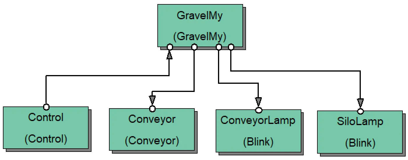
Figure 5: Gravel control system
The heart of the system is the state machine Gravel which controls all actions. The state transition diagram of the Gravel state machine shown in Figure 6 is very similar to the original state machine in the IEC document.
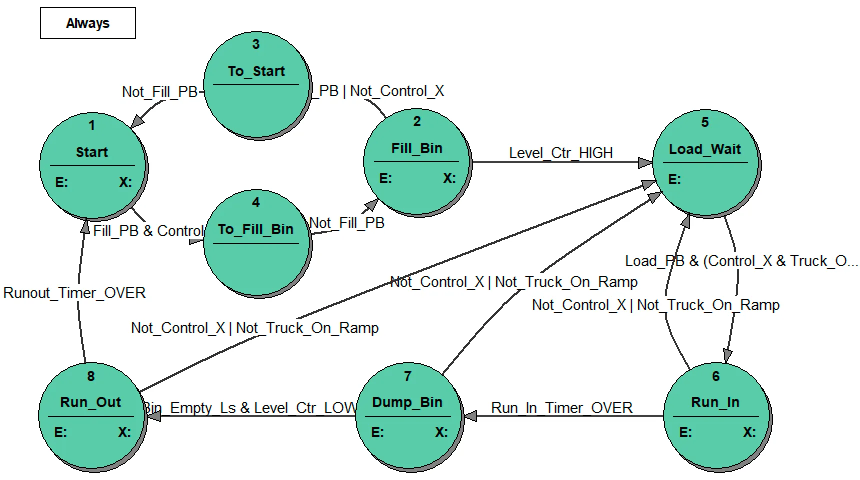
Figure 6: My Gravel state machine
We tried to improve the original state machine by adding things where we had found fault with the implementation in the IEC document. We made the improvements under the assumption that we can use only the existing hardware: sensors, actuators as well as push buttons and lamps on the console panel. Hence, we could make changes only to the control sequences. We have changed the following things:
- We assumed that the
FILLpush button is actually a momentary push button exactly as the other buttons. The 2 additional states:To_StartandTo_Fill_Binrealize the required flip-flop effect. - If the conveyor run-out is interrupted and later restarted the run-out timer is not restarted but started from the already counted value. This arrangement shortens the run-out time which otherwise is unnecessarily long. It could be improved further: we could decrease the run-out time by subtracting a value which results from the repeated run-in phase.
- The transition from the state
Dump_BintoRun_Outdepends not only on theBin_Emptylimit switch but also on the supervision of the gravel level in the bin. This is an additional security which guards against malfunction of the limit switch. - The push button
LAMP TESTnow tests all the lamps. - The siren whining is limited to few times only (a constant in the configuration which can be changed at any time). After the third
ACKNOWLEDGEthe siren stays silent independently of the state of the silo limit switch. It “recovers” if the silo becomes “not empty” again.
The difference between the implementation in the IEC document and the state machine above is that the latter contains all actions that are under its control. Figure 7 shows as an example the state transition table of the state Run_In. When entering the state, the commands “On” are sent to the Conveyor and ConveyorLamp state machines and the timer Run_In_Timer is restarted. When the timer elapses the state machine goes to the state Dump_Bin. Before the timer elapses the state machine may return to the state Load_Wait if the automatic control is switched off or the truck leaves the ramp. Leaving the state (independently of the destination state) the Run_In_Timer is stopped as the timer losses its meaning in other states.
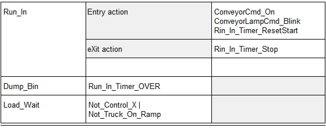
Figure 7: The state transition table for the state Run_In
There are still a few items that are missing or should be corrected:
- Malfunction of limit switches should be signalled to the operator by an alarm, but it would require an alarm display or additional warning lamp(s) on the console.
- The return to the initial state
Startin case of a limit switch malfunction is not possible.
Rearranging the role of the existing switches could allow it: the ON button could force the return to the state Start and the LOAD button could be used to stop the conveyor in states: Run_In, Dump_Bin and Run_Out. Another possibility would be to expand the functionality of the ON button: pressing the button longer (for instance 5 seconds) being treated as a break of loading forces a return to the state Start. Those revisions would require approval from the client.
Those further changes would make a good exercise for interested readers.
All details of the Gravel control system can be found in the StateWORKS project Gravel on our website. The results can be tested using SWLab and SWMon. All case studies and tools are available for download.
Conclusions
Section titled “Conclusions”Even the half-hearted in a sense “hidden” use of the state machine concept in PLC programming is a useful step forward from the intuitive way of programming by coding, into programming which is based on control system modeling. The way it is presented in the IEC example is still influenced by the “marker” way of thinking which makes it less attractive for PLC programmers. Missing a concept of a system of state machines limits the use of state machines in PLC programming to very simple examples.
The major flaw in the IEC example is that the state machine is not considered as a real solution for the application control flow. The state machine is used to store some information about the situation which covers the sunny day scenario, while the details of system malfunctions are left for the programmer: he will arrange it in some way. Problems caused by rarely-occurring malfunctions are the essence of the designer’s real task: the full advantages of correct state machine use are seen by solving those truly difficult control sequences with relative ease.
Several criteria can be used for classification of state machines. For instance, the Moore and Mealy model definitions come from the educational /scientific world. Taking the application criteria into consideration we would rather speak about: parser (in automata theory it is called also acceptor or recognizer) and control (in automata theory it is called also transducer) state machines.
The parser state machines match strings, i.e. they follow a sequence of states with the purpose of detecting a certain string pattern. In practice, they do nothing else while changing the states and the concept of output actions does not make sense for them.
A specific variant of a parser state machine transforms changes of input signals into a set of states which can be than used by simple decoding to determine outputs. Such situations occur relatively seldom and are characterized by a specific homogenization of the control requirements which happens only for rather simple control systems.
Both variants of parser state machines are special cases of state machines, finding little application in industrial control because there are not too many situations where they may be used.
The control state machines are actual state machines used in practical applications. They consist of states which determine output actions. With control state machines we are able to specify behavior of any complexity, especially by using a system of state machines.
Thinking about solving a control problem by serious use of state machines allows us to use for this purpose StateWORKS Studio. With that tool we can solve the problem and test the solution. If we are sure that it works we can then code it. An automatic translation from the StateWORKS Studio specification to an SFC program is also imaginable, why not? The best solution would be of course to use the StateWORKS run-time system and avoid the code generation.
If the control system runs anyway on a PC (it is the case for instance when using Beckhoff hardware) the use of StateWORKS run-time systems seems to be the natural choice. A simulation of a PLC run-time System on a PC would be in that case rather difficult to justify.
If the reader studies the example carefully he will see that a complete solution – within imposed limits – is presented, and not just a simplified one. It is our conviction that the complete solution to the complete problem must be produced by the design methods used, and all its behavioral features must be presented very clearly to the designer, without hiding major aspects in code or elsewhere. If StateWORKS is used the designer is encouraged – almost one might say forced – to adopt a very healthy design methodology, so ensuring that the software will be highly reliable in service.
Appendix: Testing with SWLab
Section titled “Appendix: Testing with SWLab”As SWLab has only 8 digital input switches they are used as push buttons: ON, OFF, ACKNOWLEDGE, FILL, LOAD, as limit switches: BinEmpty, SiloEmpty and as an optical sensor TruckOnRamp. The two additional inputs: LAMP_TEST and JOG are accessible in monitors (SWLab, SWQuick or SWTerm).
SWLab has 8 digital output lamps. It is sufficient for the example, and we use them for the 4 indicators: CONTROL_ON, TR_ON_RAMP, SILO_EMPTY, CONV_RUNNING and for the 4 outputs: SiloSiren, SiloValve, BinValve, ConveyorMotor.
From the 4 analog inputs that SWLab has we need only one: GravelLevel.
The rest of the objects used: timers, gravel SetPoint as a parameter, switchpoint GravelSwip to detect the gravel level in the bin, as well as state machines and their commands are accessible in StateWORKS monitors.